The site boundary is a surface solid created by using a rectangle,
polygon or polyline tool with the modifier set to 2D Surface Objects,
that is,

ABOVE: This tool combination is used to create a surface object
(specifically a closed surface object). A surface object has only
a single side, whereas a surface solid of the same object may look
the same but has two different sides.
ABOVE: The site boundary and the contour lines. Note that the contour
lines have been located each at the height that corresponds to the
contour itself. This is one of two ways to specify the contours to
the terrain modelling tool. The other method requires prepicking in
a precise order, which, most of the time, is error-prone and tedious.

ABOVE: The creek as a triangulated irregular network. The contour
lines are prepicked in any order.
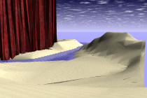
ABOVE: The terrain modelling tool is selected and the site boundary
is picked. The result is a terrain model of just the creek.
ABOVE: Blocks defined by the derivative extrusion operator using
the faces of the other part of the site as arguments. These blocks
are of a height equal to the negative of the block created in the
previous step. Using the negative of the height of the source block
means that the top face of the derivative is at the same height as
the top of the creek contour. This is critical in making the next
parts of the terrain model align properly with the creek.
The NEXT STEP:
Next, the mesh modelling option of the terrain modelling tool is
invoked (the terrain modelling tool has a red triangle on it so has
options that can be invoked by double clicking the tool.) The mesh
modelling tool has several options for the way in which it calculates
the shape of the terrain. Fall lines usually gives the best result--it
does sometimes present the problem that it is too slow for very large
models.
Now, an aside to The NEXT STEP.
One of the terrain modelling options has a very unintuitive semantics,
which, if not understood, may cost a learner many hours of frustration.
This is the site (starting) height option. The terrain modelling tool
can be applied to a closed surface object as a whole or to a face
of a solid. The site (starting) height option only applies to when
operating on a surface object as a whole.
Presume that the terrain modelling tool is being applied to a surface
object. In this case, the tool will first extrude a solid object from
the site outline to the height specified by the site (starting) height.
It then creates the terrain model. If the site (starting) height is
less than the height of the lowest contour adjacent to a site edge,
the tool will create the site such that mesh model ends at the site
(starting) height at the lowest site boundary. If the site (starting)
height is greater than the height of the lowest contour adjacent to
a site edge, the mesh model will end at the elevation of the lowest
contour. The diagram below illustrates this behaviour. Let S be the
value of site (starting) height.
A major problem arises when the desired result is that the mesh model
ends at the elevation of the site boundary (which is the case in creating
the current mutiple-terrain model and often arises otherwise.) This
cannot be achieved using a surface as the argument for the terrain
modelling tool. A face of a solid must be used.
Now presume that the terrain modelling tool is being applied to the
top face of a solid object. In this case, the tool applies the modelling
operation directly to the solid and completely ignores the value of
site (starting) height. In the following diagram let S be the value
of site (starting) height and F be the height of the face used as
an argument for the terrain modelling tool.
Returning now to the task of creating a multiple terrain model.
Back to The NEXT STEP:
For each of blocks of land bounding the creek, the contour lines
relevant to the block are prepicked, the terrain modelling tool is
picked and the top face of the solid is picked.
Finally the site components are brought together into a single object
with the union operator.
The union operator, like all the Boolean operations, requires that
its arguments be well-formed. A well-formed object is a solid—it
is bounded by a continuous unbroken surface or surfaces and, in form•Z,
all of its faces are planar. Mesh terrain models typically create
non-planar faces. While there is an option in mesh options for automatically
creating meshes made of triangles, this tends to increase the information
in the model unnecessarily as the quadrilaterals in a mesh only need
be triangulated if they are non-planar. The solution is to use the
triangulation tool to triangulate the non-planar parts of the mesh.
The triangulation tool takes a single argument, a form•Z object.
It triangulates the faces of this object depending on the settings
given in the triangulation tool options box.
ABOVE: Following is a model containing the two meshed site components
after they have been triangulated.
ABOVE: Triangulation and unioning results in a single terrain model
using different kinds of terrain modelling operations.
Using the union operator in this way is not always wise. For large
models, or for models representing logically different parts of the
site, it is often better to leave the site components as separate
solids.
In this case, the union operator has had the desired side-effect
of eliminating mesh faces over some parts of the site in which no
change in surface orientation is occurring—that it does not do
so for all such parts of the terrain model is most likely because
of differences in coordinate values at or near the limit of machine
precision.
An alternative final result would be a model in which each of the
three terrain components were left as individual solids. These components
should not overlap, so it would be necessary to difference the creek
component with each of the others. In the following diagram the three
components of the final model have been artificially separated to
demonstrate that they are different.