Overview
 |
The project was aimed at furthering personal knowledge in image recognition systems. Some algorithms used in this project are derivatives of Stereo Vision Project. The developed software implements region detection algorithms from previous project to identify uni-colored regions in both horizontal and longitudinal directions. The identified region is compared against a "memory map" to identify the best alphanumeric match for it. Project By
|

Contents:
Introduction
Just as the previous project (Stereo Vision), this project's end goal was to design algorithms which were aimed at robotic automation or integration in human society. Stereo vision algorithms are capable of depth perception but are unable to detect the pattern seen, this project was aimed at using the "regionalized" information already being generated by the stereo vision to be used for very basic alphanumeric recognition. Thus being a proof of concept that more higher level algorithms can be based on a speed and memory efficient region detection algorithms based purely on color differences in an image.
Details
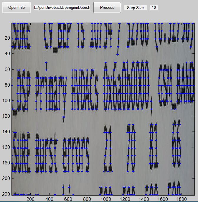
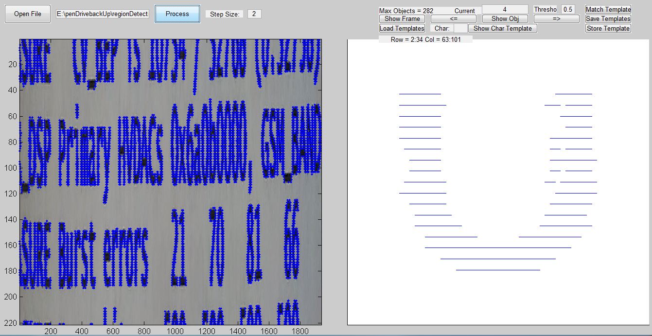
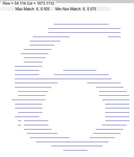
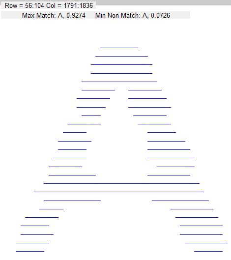
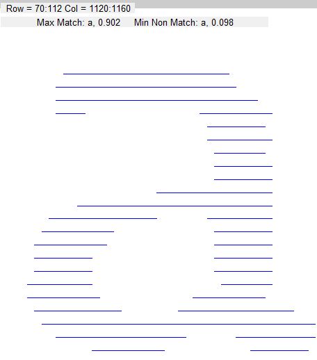
Owing to limited time available for designing and implementing the project, the software was designed as a proof of concept rather than to be fully functional and integrable. The program is based on a simple GUI which shows the result of the differential algorithms running on an image on the left. And on the right is a singular region extracted from the said image. It also displays some crucial information such as the location of the extracted region in the image, and if the "memory map" or "alphanumeric templates" have been loaded, then also displays the alphanumeric character which is the best fit. Please see figure 1.
 |
|
Figure 1: Image Alphanumeric Reader Graphical User Interface. On left blue dots indicate colored regions edges along rows. On the right a region extracted from the image, positions "Row = 2:34, Col = 63:101" is read as: the region on right spans from row number 2 till 34 and column 63 till 101 in the image on the left.
|
Region Identification
For more information on the differential algorithm being used please visit Stereo Vision Project. For a uni-colored segment of a region identified along the rows, if another segment below it is the same color, and has a major overlap across the columns with it, it is safe to say that they belong to the same region. As such the information can be recursively built to extract uni-colored regions across the rows and columns out of the images by just using the edges along the rows. This algorithm proves to be quite fast as it needs minimum information to identify uniformly colored regions. While the algorithm can generate the color of the region, it is safe to say that for a proof of concept it will not be a very crucial detail.Alphanumeric Recognition
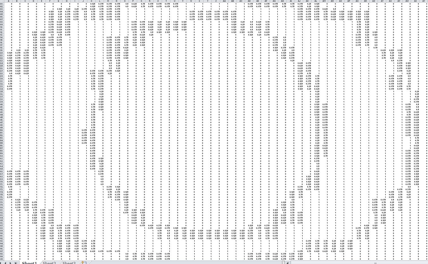
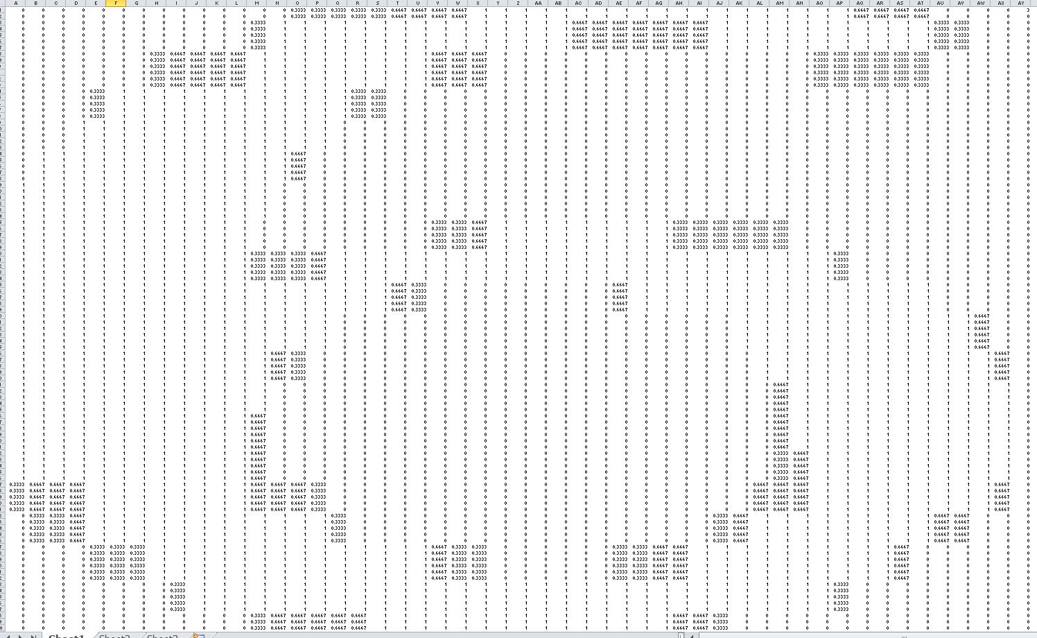
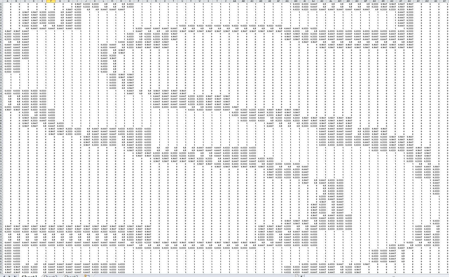
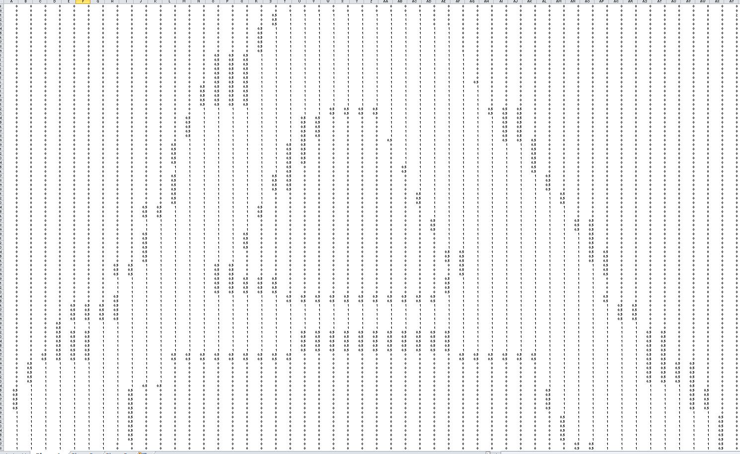
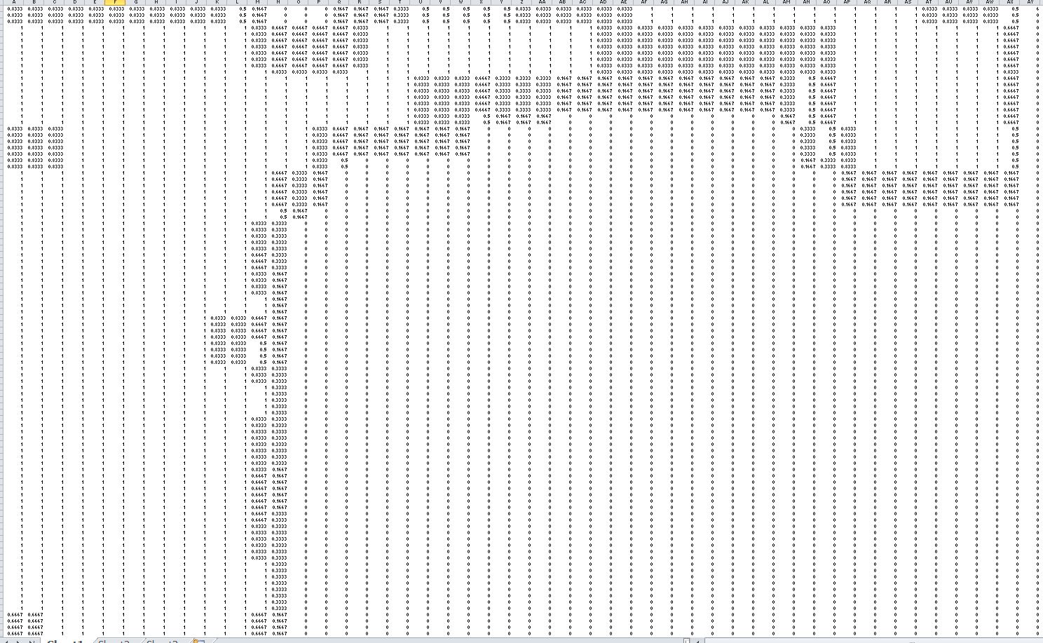
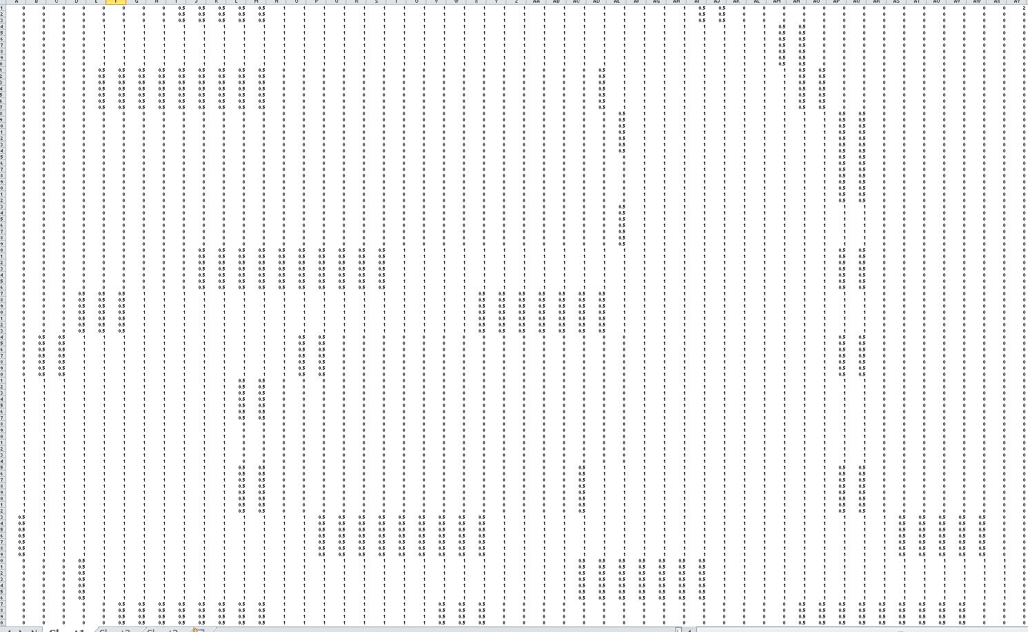
The pattern recognition is based on a "memory map" or "template", which is simply a 2-D probability matrix. Instead of finding the exact match for a pattern, the software always relies on the pattern which matches something best from its memory. This memory is built by force feeding the patterns to the software, which it stores in probability form. All the 2-D patterns can be divided into rows and columns, as these are uniformly colored, a simple identification for a region using a 2-D matrix will be allotting "1" for the pixels where the object is present, and "0" where it is not. By comparing multiple images of the same pattern the probability of each element in the 2-D memory map is calculated as the average value of the element across images, please see the images below to see this in pictorial form.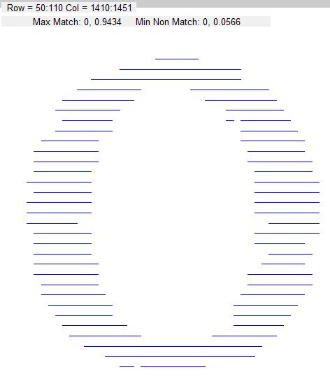 |
 |
|
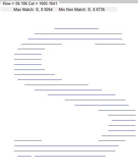
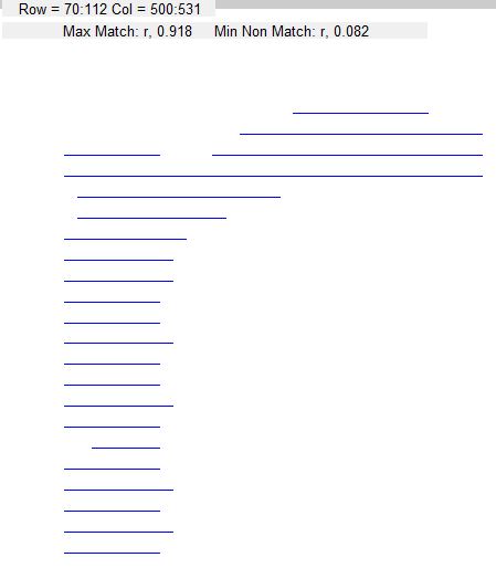
Above: a region extracted from image in Figure 1 resembling a "0". The matching ascii pattern identified by the software is given in the top left corner. "Max Match" means the best match for the pattern with the pixels being "1"/"0" where they are expected to be. "Min Non Match" means the best match for the pattern with the pixels not being "1"/"0", or in other words least deviation from expected pattern.
|
Above: Memory map showing the ascii element "0" stored in the memory. This element has been produced by computing the 2-D probability matrix for 8 different "0"s. Please save image and zoom in to see the elements of the image.
|
Some More Identified Patterns
 |
 |
 |
 |
 |
 |
 |
 |
 |
 |
Conclusion
As seen above in some of the example patterns show, the regions identified from the image do not need to be an exact match for the memory map. The system is capable of recognizing patterns from somewhat "distorted" images as well, thus as a proof of concept that this algorithm is capable of a very basic alphanumeric recognition.