Planning the track required
the stations to already by decided upon. Once this was done, it
was fairly simple to plan the track that would
connect the stations.
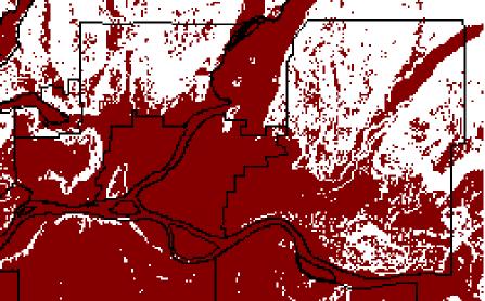
First of all, a slope map
was created using the SURFACE function with the DEM and then
RECLASS in order to find all areas in the region
that were 15 degrees or less.
Slope of 15 Degrees or less
The slope layer was then overlaid
with the landuse layer in order to find all of the possible areas
that could be used for the track route.
Once this was done, the landuse/slope layer would be able
to be reclassed in accordance with the existing
Skytrain routes landuse plan.
The values given in the RECLASS
range from 1 which is the most desirable to 1000 which is the
least desirable. The cost surface that
would eventually be created using these reclassed values was
done with the cost-push method instead of the
cost-grow method. In the cost-grow method an
absolute barrier can be defined but in the cost-push
method one cannot. I desired to have all areas
available to have a track built on them, but
only if it is completely necessary. 1000 is used to
represent a barrier. This barrier can be
passed when doing a cost surface only if it turns out to be
cheaper.
The values I used to reclass
were subjective while at the same time incorporating the desires of
the designers of the existing Skytrain.
Agricultural and open undeveloped spaces were given a value
of 1. Industrial areas, which are also
desirable, were given a value of 3. The harvesting and the
extractive layers were given a value of 10.
The less desirable areas were given values much higher.
Residential was given values from 250 to 400
depending on the type of residential. Commercial,
institutional, and transport were all given values
of 100. Finally, parks, lakes, protected areas, and
all areas that exceeded the recommended slope
were given values of 1000.
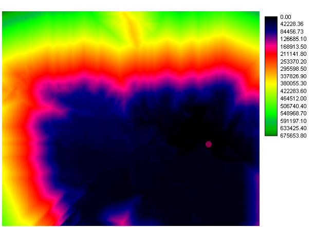
This reclassed landuse layer
was used to create cost surfaces from all of the stations that were
found earlier.
Cost Surface for Station # 1
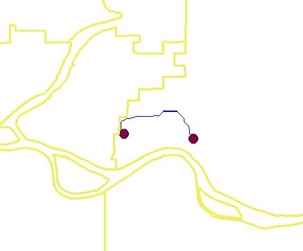
Once the six cost surfaces were made from the six
stations, the PATHWAY function was used
to find the least cost path from one station to the next. The
cost surface for station one was used
to find the path to station two. Cost surface two was used to
find the least cost path to station
three. This procedure was used all the way to cost surface six
to the Lougheed Mall Station.
Pathway from Station One to Station Two
Once all of the pathway procedures were completed, they were all combined using the
Image Calculator with the OR function. The track was then vectorized in order to make
it easier to display as one single large line.
Back to Project Page
Back to INDEX