Hardware
The vertical take off and landing capability introduced a certain challange to the hardware. Owing to the unique structure required, it was difficult to procure any pre-built aircraft fuselage which could be useful. As the structure had to handle stresses from both flight as well as hovering, it lead to a skeleton based design. In which the skeleton was made of aluminium bars and carbon rods to handle all the stresses, while the skin was fashioned from foam to absorb impacts. This page details the various calculations, design consideration, and methodlogies used for building the body of the plane.
Contents:
Airfoil
For the plane's wings, we looked up different airfoils at airfoiltools.com. After going through different airfoils and their properties, we decided to use ClarkY airfoil for our plane. We gathered the .dat file for the ClarkY airfoil containing points to plot the foil.
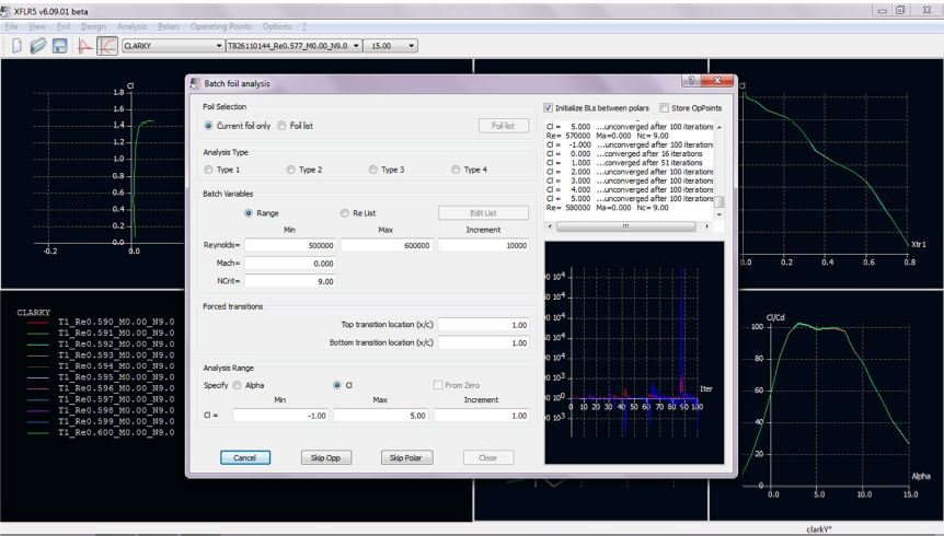
Figure: XFLR to analyze airfoils
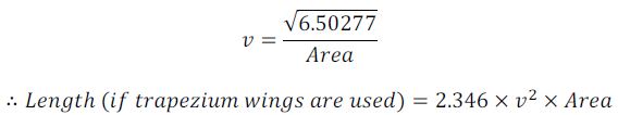
.We editted some of the points using Matlab and used XFLR5 (an open source air foil analysis software) to get the Lift and Drag coefficients at specifc cruise velocites and reynolds number. We found the thrust produced from our propellers when they are running at 20% of their max capabilities. We know that:
![]()
Wing Design
Using the equation of thrust and drag force we get the following relationship between area of wing and cruise velocity:
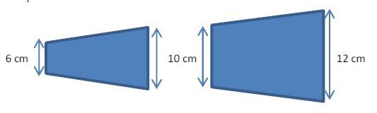
Using a velocity of 35m/s, we get a tip-to-tip wing span of 94.4cm (i.e. each wing is 46.2cm long). Assuming different heights, we fixed on a wing of the following dimensions:
For one of first attempts to construct the wing, we used 3D printed abs plastic frames and Styrofoam fillets covered in Tyvex. The frame, along with the Styrofoam, would contribute to the rigidity of the structure and the Tyvex outer covering would provide a smooth finishing of the wing profile to maintain laminar airflow over the wings.
 |
 |
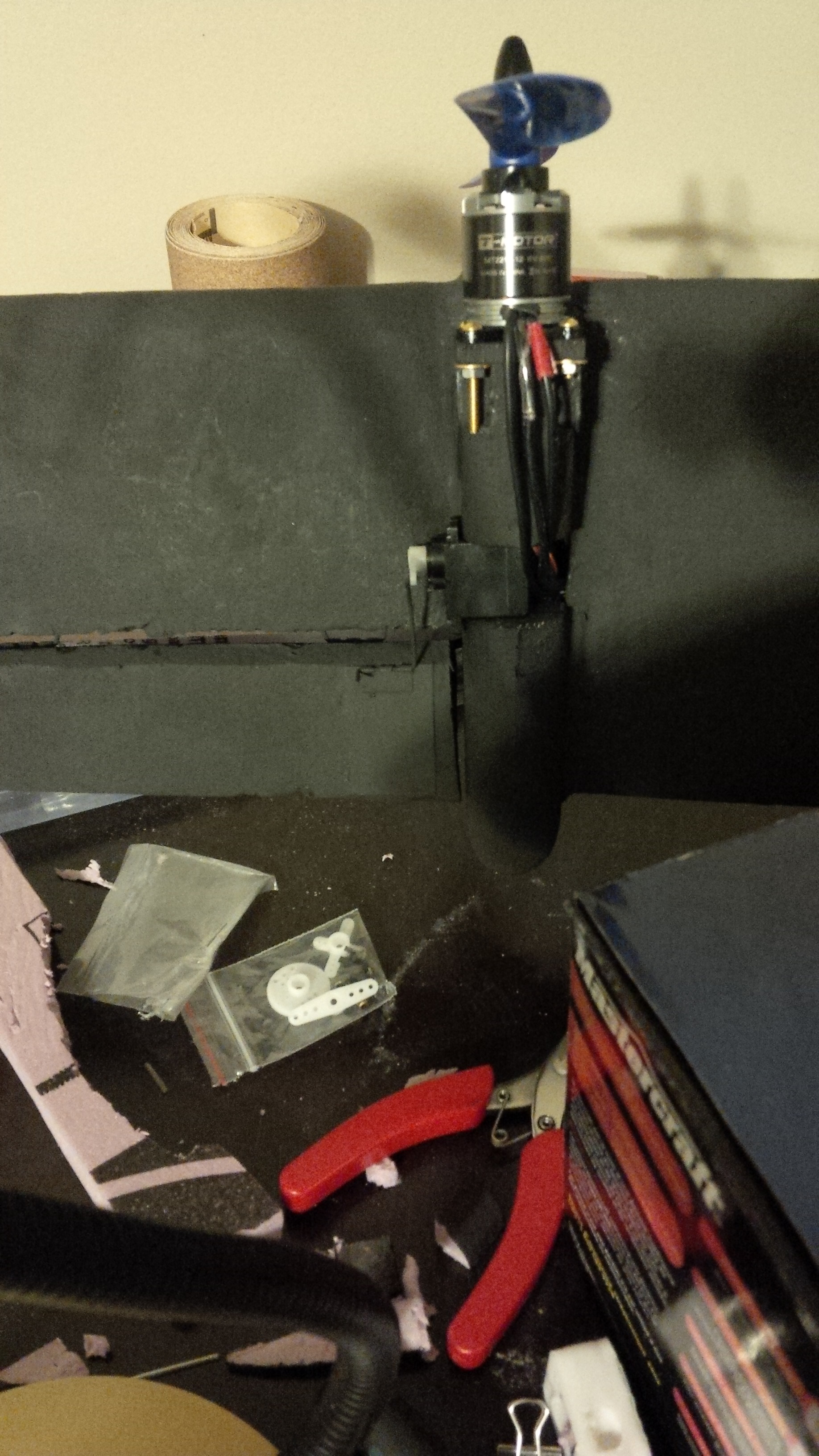
The structural rigidity of the wing was not that high as the ABS plastic plates were connected at several points simply by glue. Moreover, the ABS plastic and the Tyvex material introduced too much weight and we decided to go for other methods. Our next approach was making the whole wing with two pieces of Styrofoam as shown in the wing dimensions. The two pieces of the wing will be connected by the motor holder in the middle with two carbon rods and an aluminum bar. This would greatly reduce the weight of the wings while introducing structural rigidity at the same time. We cut approximate dimensioned Styrofoam and sanded them to attain the curvature of the airfoil with perfection. A small servo is placed on the motor holder to control the aileron.

 |
 |
|
Figures: unfinised wing, finished wings |
Figure: finished wing underside |
Prototype-I fuselage Design
The fuselage design is derived from the same airfoil curvature consisting of smaller ellipses as partitions increasing in size. We used Matlab to get the dimensions of the ellipses.
 |
 |
We cut out layers of Styrofoam with the given dimensions and pasted them with Gorilla glue. After proper sanding, the nose of the fuselage looks sharp.
 |
 |
|
Figure: layered contruction of fuselage |
Figure: finished nose section after sanding, prototype I |
 |
|
Figure: finished prototype I |
Prototype-II fuselage Design
We reiterated to a second prototype of the fuselage to efficiently design a fuselage with similar structural integrity of that of the first one but maximize the space allocation to reduce weight. We used the following dimensions for the second prototype:
 |
 |
|
Figure: raw structural parameters for prototype II |
Figure: finished prototype II |
We used similar methods as used for the first fuselage to fabricate the second prototype. We cut styrofoams in the with the dimensions from the design and glued them firmly to form one rigd body at the end. We used the same wings for the second model. After construction, the second prototype weighs apporximately 0.3kg less.
Gearbox
The current gearbox is the third iteration of the gearbox design process. The three designs are described below:
The first design was mostly influenced by the fact that we wanted minimum backlash and low backdriving capability, and based on these design requirements we chose a worm drive gearbox. However, after purchasing a light plastic worm drive set, we realized that there was still considerable backlash. Due to limited availability of light worm drive sets that met our aforementioned design criteria, we discarded the worm drive gearbox.
The second design initially included two stages of spur gears in series. The two gears in each stage had a gear ratio of 1:3, therefore the total gearbox ratio was 1:9. Later we decided to keep only one stage in favor of reducing the weight further as it also reduced the amount of couplings needed by a significant amount. Tests revealed better results but the movement was still clunky and some backlash was still present, moreover this design was also back-drivable.
 |
 |
|
Figure: solidworks model, gear box, version 1 |
Figure: solidworks model, gear box, version 2 |
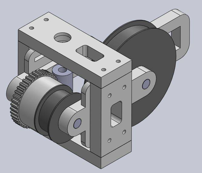
The third iteration was able to meet our original design criteria in the most suitable way. This design incorporates the previously used worm drive set along with a timing belt system. This ensure that back-drivabiity and backlash are both kept to minimum. A servo drives the worm, which transfers this power to the worm wheel, the wheel is glued to one of the pulleys in the timing belt system. Power from one pulley is transferred to the other one with the help of the timing belt, the polymer nature of this timing belt keeps the backlash negligible as it is flexible to an extent.
 |
 |
|
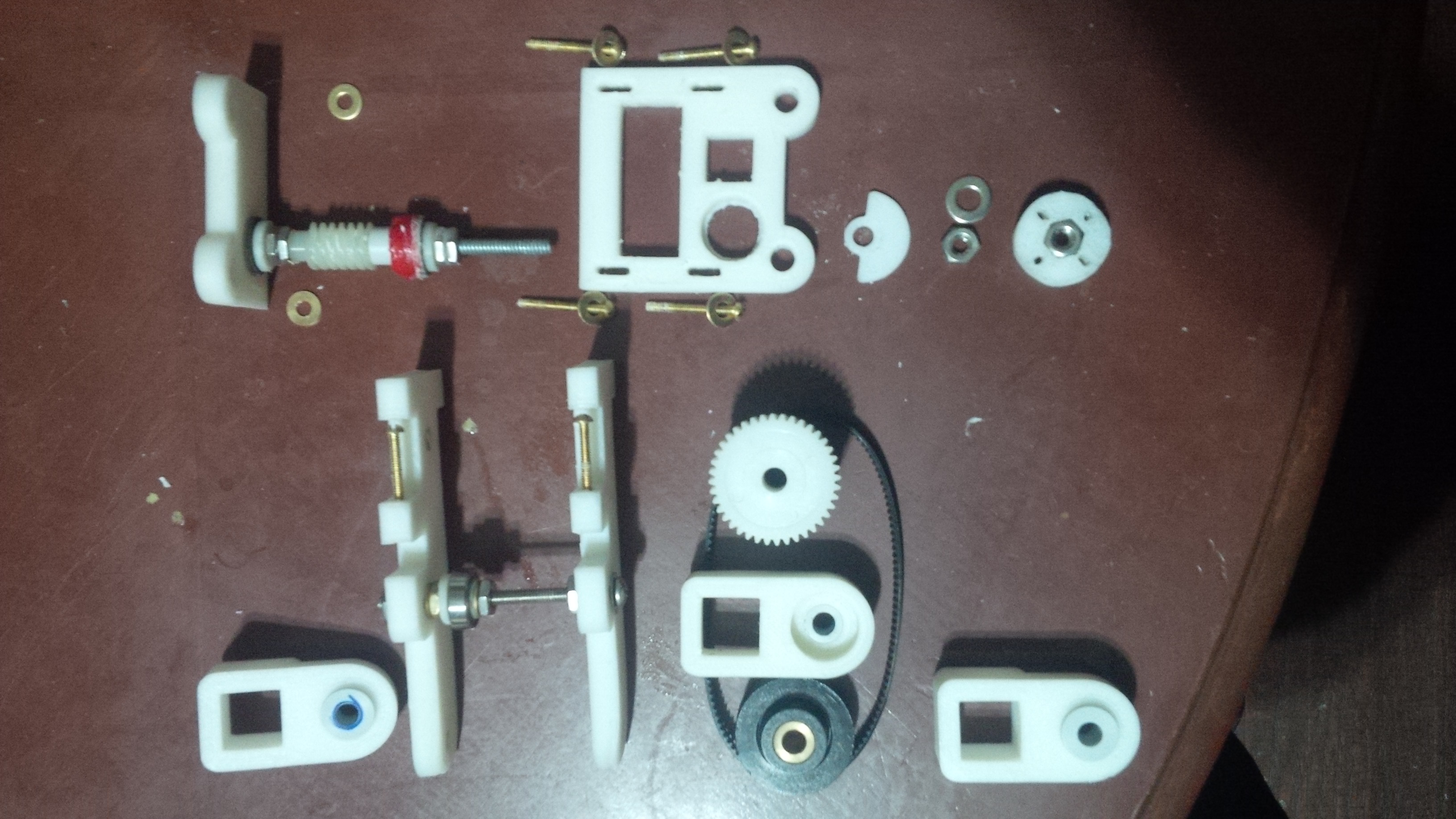
Figure: 3d printed and off the shelf components of gear box version 3 |
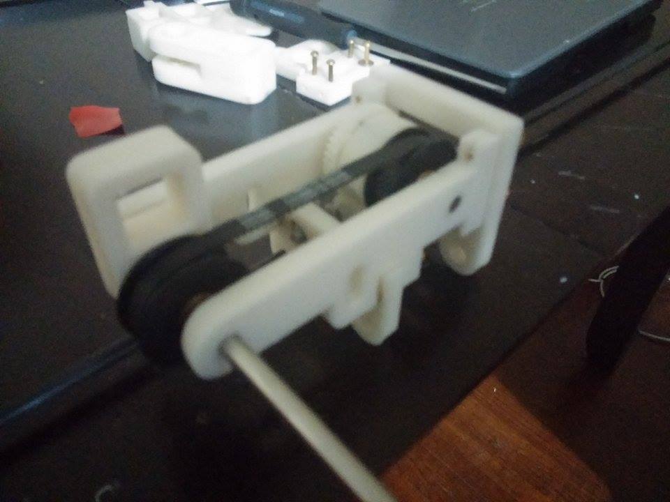
Figure: gear box, version 3, assembled |