Electronics
Most of the components in the electronics, such as power distribution, were off the shelf. The most significant piece of custom hardware under electronics was the arduino due shield, which provided quick connection points for various peripheral devices such as the IMU, GPS, XBee, SD Card, and also had on site holders for arduino Uno, and altitude sensor. The following page gives a broad description of power and communication lines setup between the various components, and information on the custom arduino due shield.
Contents:
Major Components
| MicroControllers | Description | Purpose |
|---|---|---|
| Arduino Due | 3.3 V, 84 Mhz, ATSAM3X MCU | runs "Core A" code responsible for running control algorithms and generating control signals |
| Atmega328 | 5 V, 16 Mhz, Arduino Uno MCU | First OnShield MCU is responsible for configuration and reading of GPS module over UART(Core C). Second OnShield MCU responsible for reading and processing data from attitude sensor(Core D) |
| Atmega128 | 3.3 V, 8 Mhz, Arduino Pro MCU | MCU On-Board the Inertial Measurement Unit Chip. Running "Core B" Responsible for communication with Accelerometer, Gyroscope, and Magnetometer. |
| Sensors | Description | Purpose |
| Inertial Measurement Unit | 3.3 V, 9 Degrees of Freedom, IMU | Has on-board MCU programmable through Arudino facilities. Three sensors, accelerometer, gyroscope, magnetometer, linked to the MCU by the printed circuit board. |
| GPS | 10 Hz, 66 Channel, MTK3339 | Low power, high quality, GPS for calculating x-y plane coordinate of plane |
| Altitude Sensor | Pressure/Temperature Sensor, 0.5 m sensitivity | Altitude sensor for computing z coordinate of plane |
| Quadrature Encoder | 3-D printed encoder disk, photo interrupt sensors | Attached to servo shaft in gear box for controlling attack angle of rotatable wings |
| Data Storage/Transfer | Description | Purpose |
| XBee | 3.3 V, 4 Km Range, 156 Kbps, Wireless Transceiver | Responsible for communication link between remote laptop and embedded controller. Also relays back sensory data snapshots back to laptop. |
| SD Card | 16 GB SD Card, SPI communication capable | Connected to "Core A" over SPI, used for logging run time information as well as sensor outputs, controller outputs, actuation signals and so on. |
| Actuators/Controllers | Description | Purpose |
| Brushless DC Motors | 980 KV, 1 Kg Max Thrust, 18 A Max Current | Main actuators used in both Prototype I and II. |
| EDF | 4200 KV, 0.5 Kg Max Thrust, 22 A Max Current | Main actuator used in both Prototype I. |
| Metal Gear High Torque Servo | 5 V, 5.7 Kg, 29.5 g High Torque Servo | Micro servo responsible for actuating rotatable wings through a gear box. |
| Metal Gear Servo | 5 V, 2.5 Kg, 12.5 g Micro Servo | Micro servo responsible for actuating ailerons. |
| Power Source | Description | Purpose |
| Li-Polymer Battery | 2200 mAh, 4 Cell, 40 C, 250 g | Power source used for both Prototype I and II. |
Communication Infrastructure
For data acquisition and communication, we used an Arduino Due, two Arduino Uno and an Inertia Measurement Unit (IMU) which has an embedded microcontroller unit. The Unos are connected to a GPS and an Altitude sensor respectively. The Unos and the IMU gathers raw data, processes and sends them to the Due for the controller to use. This integral data communication infrastructure comprises of the Due connected to the MCUs of the Unos and IMU via a shield. A ceramic resonator is connected to both Unos to provide a clock input independent from the Due.
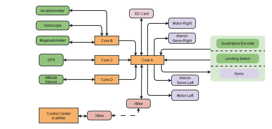
Fig: Infrastructure of the electronics showing direction of data/signals to and from the cores and peripherals.
Power Distribution
The Arduino Due is powered from the BEC and a battery to power the Due. The due has an internal voltage regulator which is used to redistribute the power from the Due to the different MCUs and internal connections. Another connection from the BEC is used to power all the different servos for ailerons and gearbox. The motors are powered directly by ESCs from the battery.
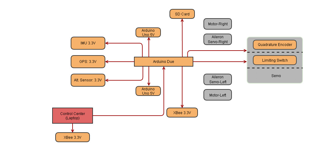
Fig: Power Distribution Network, Laptop as Power Source, for Code Upload and Sensor Test.
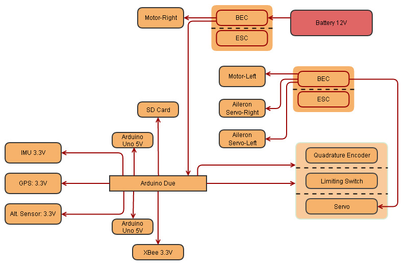
Fig: Power Distribution Network, Battery as Power Source, for Hover and Flight.
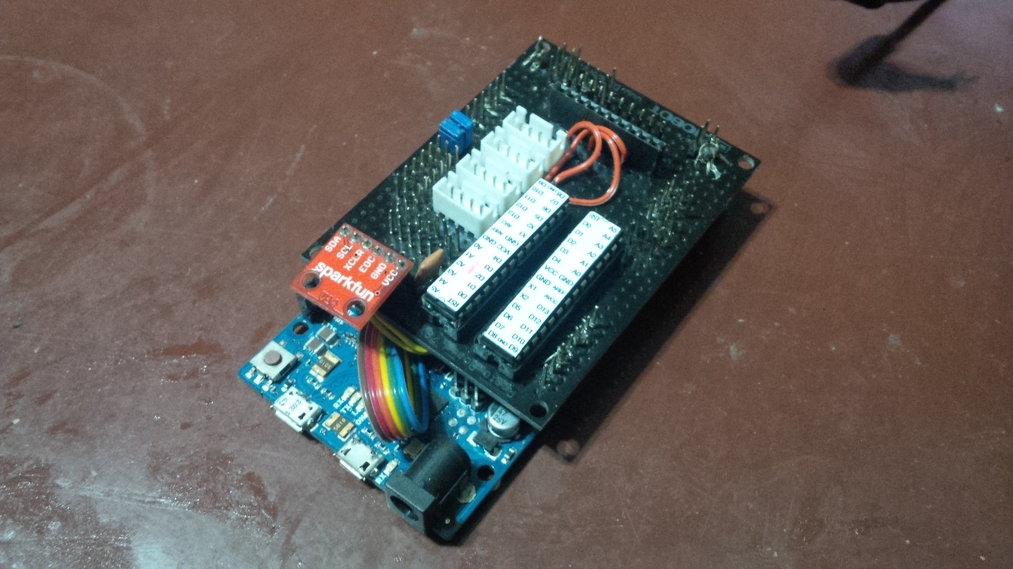
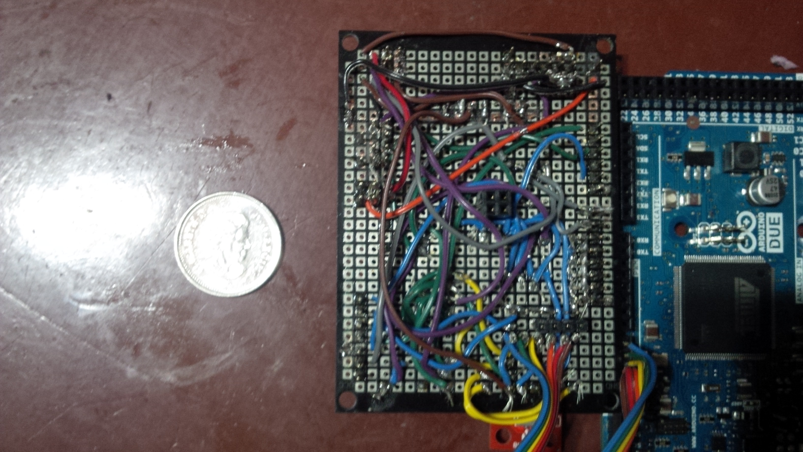
Arduino Due Shield
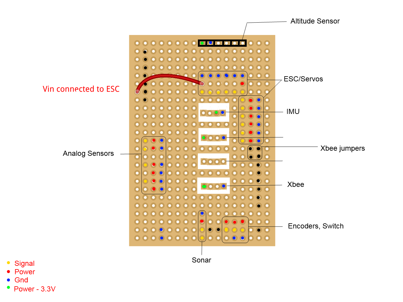
A custom "shield" for Arduino Due was designed to make the accommodation and connection of various peripherals such as ESCs, Sensors, Servos easier. The board was based on a simple perforated circuit board, with circuit established with wires. Some pins on the board exposed pins directly beneath from the Arduino Due, thus reducing the number of connections required between different points on the board.
 |
 |
|
Fig: Schematic of the shield on Core-A consisting plug and playable connections for peripherals. |
Fig: Actual shield on an Arduino Due (Core-A), underside. |