Cores
Requirement
An onboard controller for an aircraft is a real time control system, which needs to regularly obtain data from various sensors, running at different frequencies, to effectively compute and respond to various scenarios to ensure both aircraft and environment security. The system has to be capable of honoring hard deadlines, which becomes increasingly important in hovering aircrafts. Since the system has to be capable of both lower-level peripheral functions such as UART, I2C, digital pin operations, PWM, and higher level tasks such as floating points, vectors etc, as such MCUs such as ARM Cortex M0-4 easily lend themselves for the requirements.Architecture
The code system implemented on the devices was designed as a low level cyclic execution operating system with few rules in mind:- Modules/Processes: self contained code structures with two required global functions <name>_run() and <name>_init(). init() is called during system startup once, and run() is called as fast as possible to create a pseudo process.
- Each execution of <name>_run() is made sure to finish within set deadlines during development, and failure is simply post-reported but not interrupted.
- None of the processes are allowed to evoke a hardware delay, rather the functionality should be achieved using library designed for software delays, allowing OS to run other processed during the delay.
- Any data sent over the UART is packaged according to the mLogger rulesets.
 |
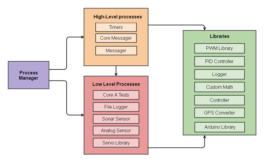
| Top level view of OS components, with arrows pointing to code structure evoked by another. |
-
Process Manager
The process manager is a dedicated component of the OS which is in charge of all the global <name>_run() functions belonging to each of the processes. It contains memory and deadline checks to selectively run and check execution time of the processes. The process manager produces pseudo-processes by cyclic execution and does not perform either time-multiplexing or interrupt generation. Any failures to meet deadlines are to be handled by the developer at the design stage thus reducing the overall complexity and reliability of the system.
-
High-Level processes
-
Timers
Timers is a high level-process which is capable of evoking registered callbacks at set intervals using software clock checks. It also contains functionality to handle software time counters for the processes, in case processes want to delay execution inside <name>_run() functions.
-
Messager
The messager(though should be spelled messenger) is a MCU side code structure performing that same function as to those of the mLogger. This process continuously looks for packaged data arriving on the UART, scans it for correct identification number and packaging length, and evokes callback to handle the data.
Processes are ranked according to a binary system as high or low level. Higher level processes are integral part of the OS and would be expected to compile regardless of the functionality and version of the MCU. Going against the rule of self containment, these processes contain select functionality with which they can evoke parts of other processes. To honor the rule of cross-platforming any execution by these processes is done using registered callback functions, thus requiring no hardcoding of the callbacks in the high-level process code itself.
-
-
Low-Level processes
All the low level processes are fully self-contained code structures with specialized functionality. Low-level processes are often MCU dependent and can be easily excluded during compilation stage. Various low-level processes were developed, such as for dealing with GPS, sonar sensor, quadrature encoder and servo, SD card etc. The OS does not provide functionality for cross-process communication as a generalized protocol often is more time consuming than dedicated function calls. Thus any development of code for cross-platform data exchange is done with extreme caution.
-
Libraries
The libraries are any section of code which do not require cyclic execution and only contain self-contained functions. Few libraries used in the project have been developed by 3rd parties, such as Arduino, SD Card etc, while some others were developed by the team such as PWM Library, PID controller, Logger, Custom Math, etc.
Implementation
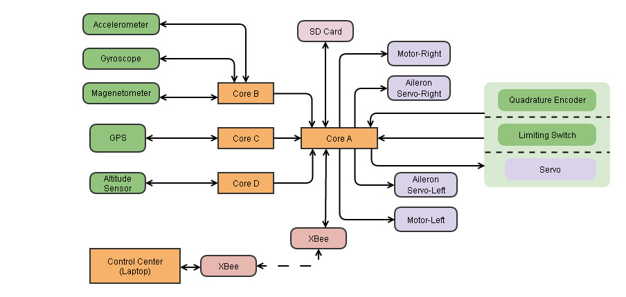
The OS core system developed was run as a distributed network system with four MCUs performing various tasks simultaneously. Each MCU was labeled as a core from A-D and were interconnected using the UART. Logging to a computer was done either through a USB cable, XBee through UART, or SD card through SPI. Following table summarizes the functionality and actions of each core.| Core Name | Function | Description |
|---|---|---|
| Core A | PID controller for hovering/flight | 100 Hz |
| X-Bee communication | Tx metadata at 10Hz, immediate Rx response | |
| SD Card Logging | 20 Hz, binary data | |
| Gearbox Servo Unit | Quadrature/limit switch reading, servo signal generation | |
| Brushless DC Motors | ESC signal generation | |
| Peripheral core communication | Data Rx from core B, C, D | |
| Core B | Sensor Reading | Accelerometer, Magnetometer, Gyroscope at 100 Hz |
| Attitude Computation | 100 Hz | |
| Core communication | Data Tx to core A, 100 Hz | |
| Core C | GPS | Setup and Reading, 10 Hz |
| Core Communication | Data Tx to core A, 10 Hz | |
| Core D | Sensor Reading | Pressure 100 Hz, Temperature 10 Hz |
| Altitude calculation | 100 Hz | |
| Core Communication | Data Tx to core A, 100 Hz |
Following is a visual representation of data flow through the distributed network system.
 |
| Above: Arrows pointing to data flow between different hardware/software modules. |