Controller
One of the main aims of the Autonomous aircraft project was to make the team members learn, research, design, and implement multi-input/output PID based controller for rigid bodies. The "controller" being referred was the mathematical component responsible for producing signals in response to the actual and desired system parameters. Under future plans was to interface the controller with a navigation system, which would produce desired system parameters for the controller to follow. This page gives broad information on research methodologies, mathematical structure, C/C++ implementation, testing and debugging of the controller.
Contents:
- Kinematic Structure of Vehicle
- Controller Design
- Embedded Implementation
- Testing
- Post Test Debugging
Kinematic Structure of Vehicle
The project resulted in production of two prototypes. These prototypes were different from a kinematic viewpoint due to the response of the system to the actuators as well as the difference in actuation mechanism used for management of the pitch of the aircraft. Following is a visual summary of the structural design of the two prototypes.
 |
 |
|
Figure: Basic Kinematic Structure, Prototype I, Hovering |
Figure: Basic Kinematic Structure, Prototype I, Flight |
In prototype I, three brushless DC motors were responsible for producing torque in x-y body plane of the aircraft during the hovering stage. While the front DC motor was planned to be shut down in flight. Controlling the yaw was done by changing the angle of attack of the ailerons on the back wings.
 |
 |
|
Figure: Basic Kinematic Structure, Prototype II, Hovering |
Figure: Basic Kinematic Structure, Prototype II, Flight |
For prototype II, two brushless DC motors were responsible for controlling the roll of the aircraft, while a servo with gearbox was responsible for changing the angle of attack of the main wings to impact the pitch of the aircraft. Yaw was once again obtained by changing the angle of attack of the ailerons of wings with respect to each other.
Controller Design
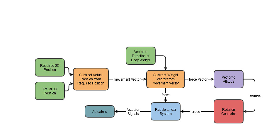
Following the rigid body control requirement and the actuator mechanisms being employed, a crude mathematical model of the controller was designed. While hovering the body produces a uni-directional thrust, while difference in the thrust from independent motors produces torque. Owing to the uni-directional thrust, any movement of the rigid body in 3 dimension can be attributed to a function of the attitude of the aircraft. Following this ideology, a rotational controller wrapped inside a position controller was designed. The crude mathematical models of the controller for the prototype I are as follows.
 |
| Figure: Control Block Structure of Rotational Controller, Version 1. |
 |
| Figure: Control Block Structure of Position Controller, Version 1. |
These models were implemented in a very simplistic Simulink model and tested for unstability.
The first version of controller were not very suitable as the aircraft was found to be not capable of producing desired torque along body-Z-axis very well. This led to the second iteration of controller for prototype I, which would involve torque production only in the body x-y plane of the aircraft. This was achieved by defining the desired outcome as to align the thrust vector with a certain norm vector, rather than attitude.
 |
| Figure: Control Block Structure of Position Controller, Version 1. |
Embedded Implementation
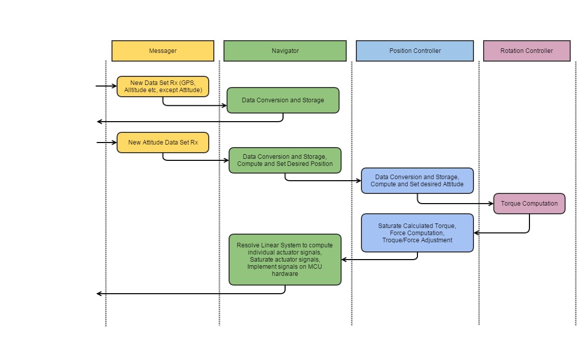
On the embedded platform, the controller was implemented as in a stack structure in C/C++, separate from the other code structures and functionalities. Within the stack structure, following was the call hierarchy from top to bottom.
- Messaging Library, responsible for receiving data from peripheral Cores over UART
- Navigator, responsible for following 3 dimensional path
- Position Controller, responsible for producing required attitude, and force
- Rotational Controller, responsible for computing torques
 |
| Figure: Architecture and Call hierarchy of C/C++ implementation. |
Separate code was designed as a library for the controllers to use, which features mathematical operations such as inverse of matrix, matrix multiplication, vector cross products etc, implemented in C. Another library was designed to facilitate PID control in C++.
Testing
Given the separation of code structure in libraries and processes. The library functions were tested using simple unit tests to check the output result based on given input. For the stack structure, the stack was tested and debugged from bottom up, starting from Rotational Controller. At each stage the output being produced was visually inspected for validity for some selective scenarios. A simple rigid body simulation was used to observe the effect of torques and forces being handed by the stack structure and simulations were carried out in a interaction loop between the rigid body simulator and the stack structure.
After the simulated tested was complete, testing on real-life system was initially carried out in constrained jigs. As such only two actuators were used, with only one degrees of freedom, and the IMU acting as the sensory input.
After the jig testing produced credible results, the full system was tested by simply holding it down and allowing movement only along certain degrees of freedom. This process was extremely iterative, with the requirement to collect the data, observe optimization requirements, updating code structure and so on. Testing proved to be the most demanding of the activities of the whole project, owing to the fact that the team did not have access to a warehouse for testing, which required driving out to fields, testing, updating and going back at some other time to test the update. Given the time consuming nature of this process, it was the single biggest reason leading to the decision of freezing the project, apart from the team members getting more involved with school workload.
Post Test Debugging
Given the iterative and out-in-field nature of the testing process, post processing of the collected data was a major step in identifying bugs as well as optimization points. mLogger was crucial in this step as well, as the data from the embedded platform was saved in binary from to a SD card. mLogger was capable of parsing the data into DLM files. the DLM files were read through matlab scripts to study data in graphical form. For more information on post processing please visit the post processing page.