ENSC 220
ELECTRIC CIRCUITS I
Lab #3: RL and RC Circuits
OBJECTIVE:
You will wind (and test) your own inductor, which you will
also use in the AM radio project in a subsequent lab.
You will also investigate the properties of capacitors by making a simple
capacitor and by designing and testing filters and a simple capacitive switch.
PREPARATION:
Read Lab Handbook 2.3.4 (Capacitors) and 2.3.5 (Inductors)
Read Appendix III (pp. 227) on standard capacitor values.
EQUIPMENT:
Basic lab tools and breadboard
Dual DC power supply
Digital Multimeter (DMM), Fluke 8010A
Function Generator, Wavetek 182A or equivalent
Oscilloscope, Tektronix 2235 or similar
LRC bridge
Operational amplifier, TL072
Light emitting diode
Resistors
Capacitors
Connnecting wire
Wire and core for inductor
Emery paper
Tape
Materials for capacitor
NOTES:
When making circuit changes, turn down the current on the power
supply and turn off the power supply. Turn it on again only after
checking the circuit carefully.
Check the multimeter setup before hooking it into the circuit.
Improper setup can give incorrect readings and/or damage the meter.
Lay out your circuit neatly and logically on your breadboard to
facilitate subsequent changes or troubleshooting.
When operating the op amp from a single supply, note that the other
power supply input on the op amp must be grounded.
Be sure that DC offset on the function generator is set at "0".
Use maximum power supply voltages of +/- 12 volts.
After sanding the insulating varnish off the taps on your inductor,
you may need to tin them to be sure that all insulation is gone. Note
that this cannot be done with the continuously variable inductor,
because turns could be shorted by solder.
Use tape to secure taps and ends of windings on your inductor.
METHOD:
INDUCTOR:
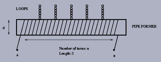
1. Construction the inductor.
The inductance L of an air-core inductor is approximated by:
L = (d^2 n^2)/(18d + 40l)
where:
L = inductance (measured in uH)
d = coil diameter (inches)
l = coil length (inches)
n = number of turns.
You will be supplied with #26 AWG enamelled wire (0.0170" diameter) and a
5" piece of nominal 3/4" (actual O.D.1-1/16") plastic pipe to construct your
inductor (you should not need any more than 30' of wire). You will probably
want to experiment with inductances in the range of 50 - 200 uH when you
finally build your AM radio. You can build a "tapped" inductor by inserting a
twisted wire loop "tap" at several sites along the inductor length:
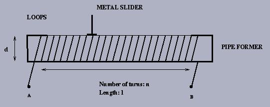
Alternatively, you can build a "variable" inductor by winding the inductor,
then use a piece of emery cloth (or fine sand paper) and lightly sand off
the enamel wire coating. Then run a metal "slider" across the exposed
windings to set up a variable tap:
2.
Use the LRC bridge to measure your total inductance and that of each tap.
Compare to calculation.
3.
Also devise your own method to measure the total inductance (e.g., based on
a step-response technique) using the terminal characteristic for an inductor:
v = L di/dt . Compare to calculation.
CAPACITOR:
1. Construct a capacitor.
You can make a capacitor with two metal plates (cross sectional area A)
separated by a dielectric of thickness d. Capacitance is determined by the
formula, C = eA/d (where e is a constant determined by
the material between the plates - the dielectric).
Construct a capacitor using any material you choose (plates: tin cans,
coins, tin foil, etc., dielectric: air, plastic film, paper, etc.).
2.
Measure the capacitance of your capacitor using the LRC bridge.
3.
Also devise your own method (e.g., based on a step-response technique)
using the terminal characteristic for a capacitor: i = C dv/dt.
4. HIGH PASS FILTER:
Construct a simple RC high pass filter circuit, using your capacitor.
With input level constant, sweep the input over a wide range of frequency
(sine wave), and plot the output level response.
Repeat above using a capacitor of, say, 330 to 1000 nF instead of your
capacitor.
Repeat using a capacitor of, say, 15 to 100 pF instead of your capacitor.
5. LOW PASS FILTER:
Construct a simple RC low pass filter circuit, using your capacitor.
With input level constant, sweep the input over a wide range of frequency
(sine wave), and plot the output level response.
Repeat above using a capacitor of, say, 330 to 1000 nF instead of your
capacitor.
Repeat using a capacitor of, say, 15 to 100 pF instead of your capacitor.
6. CAPACITIVE SWITCH:
Use your capacitor (along with an op amp(s) circuit) to produce a simple
capacitive switch. The switch should be designed to operate as follows:
Pressing on the capacitive element should alter its capacitance.
Explain how.
Assuming a sinusoidal input, devise a circuit whose output amplitude
depends on C. Experiment with different frequencies from 10 kHz - 1 MHz,
and possibly with the R and C in your circuit, to obtain a maximum change
in output level when your capacitor is pressed. If possible, try to get at
least a 1.5x to 2x level change.
Measure the change in this output using a simple comparator circuit.
Process the output of this comparator so that you get a DC signal that goes up
and down as you press on your capacitor. This can be done by choosing and
setting an appropriate reference voltage on the comparator.
The comparator output should "switch" on an LED through a current limiting
resistor as shown below.
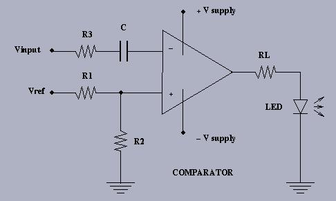
The resistor RL inserted between the comparator output and the LED is
used to limit the current through the LED.
You can try several resistors to adjust the intensity to your liking. The
LED conducts current in one direction only (in the direction of the arrow)
so you may have to reverse the LED connections if it does not light the
first time.
If you want to read more about diodes (the device you are using is a Light
Emitting Diode - LED) then you can refer to Chapter 6.
Your lab write-up should investigate a number of considerations
(design, analysis, measurements, observations, testing, calibration, etc.)
for all these experiments.
Last modified: hu Aug 13 20:03:59 PDT 1998.