METHOD:
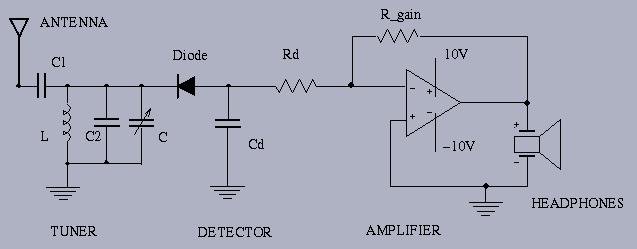
AM radio circuit:

MODEL OF THE ANTENNA:
We use a simple long wire antenna (about 60' long) that is
strung between two posts on the roof above the Lab ASB 9800.
A coaxial feed-line drop from the antenna and a green wire attached to a cold water pipe
(earth ground) is available at workstation #31).
We have found that the antenna can be modeled
using a series-resonant LC circuit.
Think of the
antenna as an AC voltage source generating AM signals in the band
from 550 to 1600 KHz.
This AM source is then coupled to your receiver through a series LC circuit.
TUNER: You can start the design the tuner section. Pick a relatively strong AM station (CKLG 730, CKNW 980, ...,) and determine the approximate value of inductance L that you would need to add to the circuit to achieve resonance at the desired frequency. You do not have to determine L exactly because you can use fixed and variable capacitance C to fine tune to the AM station. Connect your inductor/breadboard assembly to the test jig/antenna/ground/test equipment (at workstation #31). Experiment with different values for L and C. How many stations can you locate? What is the bandwidth of your receiver and how does this affect your channel selectivity?
AM DETECTOR:
The detector is comprised of the diode, resistor Rd, and
capacitor Cd. This section of the circuit is used to
rectify the received AM sinusoidal signal and
to ``smooth'' out the ripple so that you can improve
the fidelity of the audio signal.
Start by choosing an appropriately large value for Rd so that it
does not load the received signal significantly.
Then observe the received rectified signal on the oscilloscope.
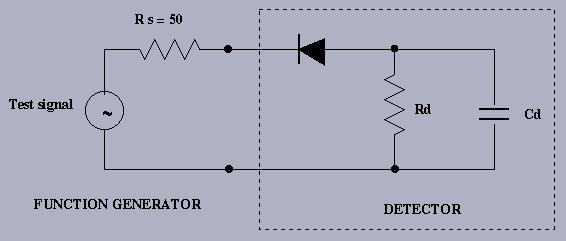
As you add the capacitor Cd, you can smooth out the ripple. One way to determine Cd is to connect the function generator to the detector and adjust the frequency to correspond to the AM carrier frequency. Then select Cd to achieve visible ripple. What happens if Cd is too small? What happens if Cd is too large? The capacitor Cd should be chosen so that it works well with several received AM signals.

AUDIO AMPLIFIER:
The final section of the AM radio is used to amplify the
audio signal to a sufficient level to
drive a pair of ordinary headphones.
Measure the resistance of your headphones.
(Note that this measurement will yield the DC resistance rather than the impedance
of the headphone transducer element(s).)
We are dealing
with a monophonic signal so you can connect each headphone
(Left or Right) in parallel or series to the
amplifier output. Which is better?
Experiment with different gains of the op-amp section
and select a suitable value for R_gain.
DISCUSSION:
Discuss the methods you used
to design each section of the radio. Why do we use an
inverting amplifier in this circuit?
Could you design the radio using a non-inverting amplifier?
Discuss the features of your radio in terms of the station
tuning range and selectivity.
What improvements could you make to the circuit to yield a better design?
How portable is your circuit? Try the radio with your own antenna.
Last modified: Sunday October 14 21:42:51 PDT 2001.