Software and Control
Controls to integrate the hardware peripherals comprised of different components including filtering and fusion the raw data from the inertial measurement unit, taking a moving average of the acquired data and finally controlling the servos according to the feedback from the headset.
Contents:
Complementary Filter
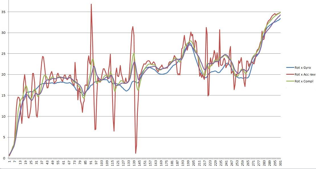
After researching different methods to filter and fuse the sensory data from the inertial measurement unit, a Complementary filter was used to do so. It was necessary as the raw data was from the accelerometer would react very strongly to small changes and the gyroscope would readings would drift over time. A complementary filter would fuse these two datasets to give a very precise reading. The graph below shows the necessity and effectivity of a complementary filter.

Figure: Effect of complementary filter on noisy IMU data (rotation about x-axis depicted here). Gyrometer data is shown in blue color, accelerometer data in red, and complementary filter in green.
Moving Average
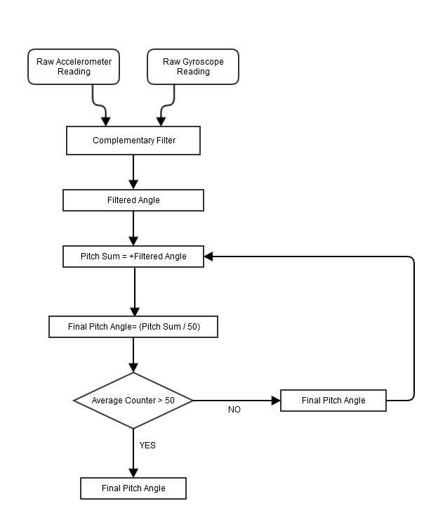
The gimbal IMU (MPU6050) is a 6 degree of freedom inertial measurement unit providing information of roll pitch and yaw using gyroscopes and accelerometers. This is one of the reasons, a complementary filter would work but in large resolutions only. These spikes would result in an uneven controller. This was countered by taking a moving average. A function would take in 50 readings and average it out and pass it on to the controller. This was very effective in dealing with spikes in the consistent readings. The algorithm used can be seen below:

Figure: Moving Average Flowchart.
Controller
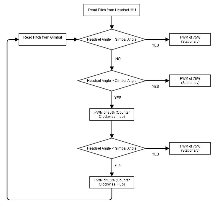
After filtering out the raw data and fusing the sensory data and taking an average of the filtered data, the processed data is used to control a desired orientation depending on the feedback of the remote IMU. The microcontroller adjusts the gimbal by moving the servos up or down (counter clockwise or clockwise) by applying modulating the pulse width to the servos as discussed before. Essentially, the gimbal always tries to match the incoming IMU reading from the headset to the IMU reading of the gimbal. This creates a close loop system to control the camera attached to the gimbal. The gimbal servo moves up if the IMU reading of the gimbal is less than the headset IMU and moves down if the gimbal IMU is more than the headset IMU. It stays stationary if the two IMUs are at a similar orientation. The resolution of the IMU is nearly 10 degrees to compensate for small drifts in the sensory values. The controller algorithm can be seen below

Figure: Controller Flowchart.