Communication
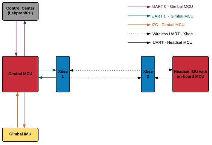
As this project uses a number of devices for different tasks, robust communication among these devices is necessary for optimal performance.

Figure: Mapping of communication peripherals used in this project.
Contents:
I2C
The gimbal IMU (MPU6050) supports I2C communication which can be used to retrieve data from the IMU. The gimbal MCU (TIVA C) communicates with the sensor using its I2C1 module. The communication process starts with the MCU commanding the sensor to wake up. Then the MCU sends the slave address followed by the register address. The sensor responds by sending the value of the corresponding register address to the MCU.
The flowcharts below depicts the algorithm used for I2C communication
| |
|
UART
UART module 1 of the gimbal MCU (TIVA C) is used to communicate with the headset IMU. The headset IMU has an onboard ATMEL ATMEGA328 microcontroller which is programmed to serially send data in the following manner:
| Byte 0 | Byte 1 | Byte 2 | Byte 3 | Byte 4 | Byte 5 | Byte 6 | Byte 7 |
|---|---|---|---|---|---|---|---|
| 'y' | <Yaw Value> | 'p' | <Pitch Value> | 'r' | <Roll Value> | 'y' | <Yaw Value> |
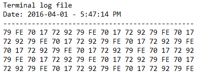
A snippet of a log file logged by a serial communication terminal window program shows the data from the IMU received by the PC via USB in figure below

Figure: Serial data output from the headset IMU logged in hexadecimal values.
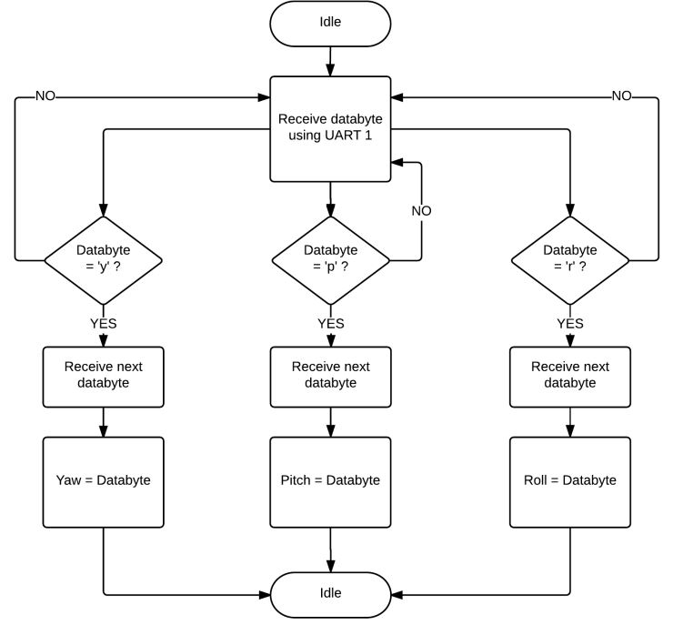
In order to read the serial data received by the TIVA C microcontroller, the following algorithm is used:

Figure: Flowchart depicting algorithm used by TIVA C microcontroller to interpret headset IMU data.